The articulated models (Figure 1) have hierarchical structure where
each link has its own coordinate system (CS) and is positioned relatively
to the CS of the previous link. The position of the link ![]() in the CS of its
predecessor is described by the joint angle. Thus, every joint transformation
is local. That fact assists in operations with hierarchical articulated
structure (Figure 1). The transformation from the CS of any given link
in the CS of its
predecessor is described by the joint angle. Thus, every joint transformation
is local. That fact assists in operations with hierarchical articulated
structure (Figure 1). The transformation from the CS of any given link ![]() to the world CS is given by concatenation of partial transformations between
each two neighbor links from the base to the given link.
to the world CS is given by concatenation of partial transformations between
each two neighbor links from the base to the given link.
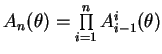
The first link in the articulated structure is a base. The end of the structure is an end effector. The position and the orientation of the base is expressed in the global coordinates. Every articulated structure has one or more end effectors and the motion control of the structure is done through these end effectors. In many cases, the end effector takes place at the end of the structure, like palm, finger, foot, head, etc.
The state of the articulated structure is represented by a state vector
![]() in
the joint (angular) space. The position and the orientation of the end effector is
represented by the end effector position
in
the joint (angular) space. The position and the orientation of the end effector is
represented by the end effector position
![]() in Cartesian space. The relations
between the state vector
in Cartesian space. The relations
between the state vector ![]() and the end effector
position
and the end effector
position ![]() are expressed by equations (1) and (2).
are expressed by equations (1) and (2).
| Forward kinematics | Inverse kinematics |
|
|
|
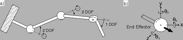
The complexity of the articulated structure is expressed by the term degree of freedom (DOF). The DOF of the articulated structure is the number of independent variables necessary to specify the state of the structure.
For example, if the joint could revolute in ![]() axes, the degree of
freedom of that joint is
axes, the degree of
freedom of that joint is ![]() . When the structure (Figure 2a)
consists of three joints and two of them could revolute in two axes and
one could revolute in one axe, the DOF of that structure is 5.
. When the structure (Figure 2a)
consists of three joints and two of them could revolute in two axes and
one could revolute in one axe, the DOF of that structure is 5.
The notation for some characteristics differs in various works. The terms in this paper are defined as follows:
State vector (angles)
![]()
Transformations (generally) from link ![]() to link
to link ![]()
![]()
Initial (base) global transformation of articulated structure ![]()
Total end effector position in the global coordinates
As the inversion of the function ![]() is not trivial in all cases,
a number of approaches solving the computation of the state vector
has been proposed. The next section gives an overview of several
such methods.
is not trivial in all cases,
a number of approaches solving the computation of the state vector
has been proposed. The next section gives an overview of several
such methods.