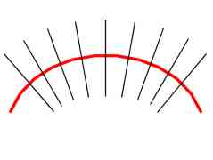
Fig. 1: Bent axis and slicing planes.
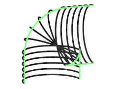
Fig. 2: Selfintersections due bending.
Before we start to explore ways of their generalization, we will take a closer look at solids of revolution itself. There is one axis and one curve on the input side and one solid of revolution on the output side. The curve is two-dimensional. In common set-up, axis is one of the main axis of coordinate system (usually z) and curve is located in xz plane (often only in half-plane with positive x-coordinates). By rotation of plane xz around z-axis, curve follows circular path. In other words, every point of curve creates circle in plane perpendicular to axis. Such planes are later referred as slicing planes or slices.
To summarize basic construction scheme (that will later be generalized): Given an axis and a curve to rotate, make slicing planes (planes perpendicular to axis). Create circle from each intersection of slicing plane and curve. Centers of circles lie on axis.
Generalization itself can be divided into several stages (next three chapters).
The first generalization comes in form of bent axis. Slicing planes are no more parallel, but rather perpendicular to axis (figure 1 shows bent axis and several slicing planes). Creating circles in slicing planes follows the same rules as solids of revolution are using [Ferk00].
|
Fig. 1: Bent axis and slicing planes. |
Fig. 2: Selfintersections due bending. |
Allowing for bent axis, we resign to straightforward control of selfintersections. Solid of revolution can have selfintersections only if rotated curve has selfintersections. Neighboring slicing planes intersect. Area of intersection is determined by curvature of axis. Everything inside of radius of curvature in certain slicing plane cannot produce intersections due bending. Selfintersections are present at inner side of curvature (see cut of object at figure 2).
Center of circle(s) in slicing plane is a point of intersection between slicing plane and the axis. What happens when we use more than one axis? There can be more intersections of slicing plane and axes. Now every point of rotated curve, instead of curve, will follow "circle with multiple centers". How does such beast look like? It is an isocurve in the slice and is called generalized conic (or n-Ellipse [Seki99]). Weighted sum of distances form all foci is constant for every point of generalized conic (see formula 1 and figure 3). The constant is determined by value at intersection point between slicing plane and rotated curve [Ferk00]. Term focus has historical roots in naming of two special points inside ellipse. Later when curves with more special points arrived, term focus was adopted for them [Camp82]. More about generalized conics can be found in chapter 3.
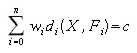
Formula 1: Definition of generalized conics. X is any point of curve, Fi are foci, wi is weight of focus i, di metrics of focus i and c is isovalue of curve. |
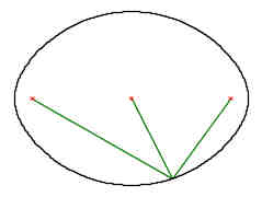
Fig. 3: Generalized conic construction. |
Having several axes, slicing plane can be perpendicular to all of them only in special cases. Therefore, we need additional curve, which can determine normal of slicing plane. This curve is called leading curve and has not other reason, than determination of slicing planes' position and orientation. In other words, axes have no more influence at bending. It is exclusively done by bending a leading curve.
Distance measurement for creation of generalized conics is not restricted to use of Euclidean metrics. Quite interesting results are obtained with Manhattan metrics. While Euclidean metrics creates smooth generalized conics, Manhattan one creates polygons. It is also possible to use different metrics for different foci (axes). Having two identical axes with different metrics, we can blend them together and create smooth transition between circular and square slice (figure 4). Detailed description of modeling is given in chapter 6.2.
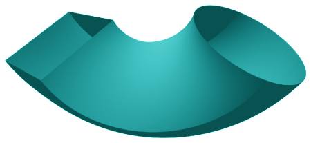
Fig. 4: Square to circle transition using blend between Manhattan and Euclidean metrics. |
Manhattan metrics introduces sensitivity to orientation of coordinate system (see figure 5). Rotating coordinate system, shape can change significantly. Consistent orientation of coordinate system in neighboring slices is necessary. One of possible solutions is to rotate coordinate system to align z-axis to normal of slice. Translated axes x and y will create local coordinate system.
More details on usage of various metrics are given in chapter 3.
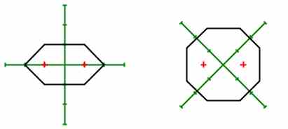
Fig. 5: Changes in shape of generalized conics for Manhattan metrics when coordinate system rotates. |
By introduction of multiple axes, bending becomes more problematic. Small bending (lower than 90 degrees) is not influenced. Higher bending angles can cause occurrence of additional foci in a slice. They are caused by intersection of slicing plane with parts of axis, which are distant from expected set of foci. Due this reason it is not possible to model torus.
This restriction can be bypassed by declaration of segments. Every segment contains part of leading curve, part of each axis (void part is considered legal) and part of rotated curve. Segment is threatened as standalone generalized solid of revolution for purposes of slice creation. Segments are joined to create generalized solid of revolution. Not whole solid have to be covered by segments (this way you can create gaps in it).
As an example of segment usage, here are two pictures. Torus (figure 7) can be created using three segments. Leading curve and the only axis are identical circles, rotated curve is scaled and moved circle. Every circle is divided into three equally sized pieces (that create segments).
The second example is shell (figure 6). It is divided into nine segments way analogous to torus. Detailed description how to model shell (but using special version of generalized solid of revolution rather than segments) is given in chapter 6.
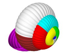
Fig. 6: Modeling of shell using segments. |
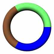
Fig. 7: Modeling of torus using segments. |